
1
/
of
1
Satcom Solutions
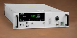
Amplifier, TWT , Ku-Band, 400W
Amplifier, TWT , Ku-Band, 400W
- Specification Model VZC-6964
Frequency 5.850 to 6.650 GHz
Output Power
TWT 400 W min. (56.02 dBm)
Flange 350 W min. (55.44 dBm)
Bandwidth 800 or 1225 MHz, depending on configuration
Gain - 75 dB min. at rated power output;
- 78 dB min. at small signal
RF Level Adjust Range 0 to 20 dB
Gain Stability ±0.25 dB/24hr max, at constant drive and temperature;
±1.0 dB over temperature, -100C to +500C
Small Signal Gain Slope ±0.02 dB/MHz max.
Small Signal Gain Variation
0.6 dB pk-pk across any 40 MHz band;
4.0 dB pk-pk max. across full band;
4.5 dB pk-pk max. across full band with linearizer option
0.6 dB pk-pk across any 40 MHz band;
4.0 dB pk-pk max. across full band;
6.0 dB pk-pk max. across full band
with linearizer option
0.6 dB pk-pk across any 40 MHz band
2.5 dB pk-pk max. across full band;
4.5 dB pk-pk max. across full band
with linearizer option
Input/Output VSWR 1.3:1 max., 1.3:1 max.
Load VSWR 2.0 max. continuous operation; any value for operation without damage
Phase Noise
Phase Noise Profile
AC Fundamental
Sum of All Spurs-12 dBc better than IESS 308/309 specification; -42 dBc/Hz at 10 Hz; -72 dBc/Hz at 100 Hz;-82 dBc/Hz at 1 kHz; -92 dBc/Hz at 10 kHz; -102 dBc/Hz at 100 kHz; -122 dBc/Hz at 1 MHz-42 dBc-50 dBc
AM/PM Conversion 2.50/dB max. for a single carrier at 6 dB below rated power for 5.85 to 6.65 GHz configuration;
3.00/dB max. for all other configurations
Harmonic Output-60 dBc at rated power, second and third harmonics
Noise Density
<-130 dBW/4 kHz from 3.4 to 4.2 GHz
<-65 dBW/4 kHz in passband
(<-60 dBW/4 kHz with linearizer option)
<-110 dBW/4 kHz from 12.0 to 40.0 GHz
Intermodulation-24 dBc or better max. with two equal
carriers at total output power 7 dB
below rated single-carrier output (at 4
dB with optional integral linearizer)-23 dBc max at 7 dB OBO (at 4 dB OBO with linearizer)
Group Delay In any 40 MHz band: 0.01 ns/MHz linear max; 0.001 ns/MHz2 parabolic max; 0.5 ns pk-pk ripple max.
Primary Power 110-240 VAC ±10%, single phase 47-63 Hz
Power Consumption 1.35 kVA typ; 1.35 kVA max.
Power Factor 0.95 min.
Ambient Temperature-100C to +500C operating; -400C to +700 non-operating
Relative Humidity 95% non-condensing
Altitude 10,000 ft. (3,048 m) with standard adiabatic derating of 20C/1000 ft. (305 m) operating;
40,000 ft. (15,240 m) non-operating
Shock and Vibration Designed for normal transportation environment per Section 514.4 MIL-STD-810E.
Designed to withstand 20G at 11 ms (1/2 sine pulse) in non-operating configuration.
Acoustic Noise 65 dBA @ 3 ft. from amplifier
Cooling (TWT) Forced air with integral blower. Rear intake and exhaust.
RF Input Connection Type N Female
RF Output Connection CPR-137G waveguide flange, grooved with UNF 2B 10-32 threaded holes
RF Output Monitor Type N Female
Dimensions (W x H x D) 19 x 5.25 x 24 in. (483 x 133 x 610 mm)
Weight 70 lbs (31.8 kg) max.
Share
Request a Quote
Fill out the form below and we'll get back to you with a personalized quote.